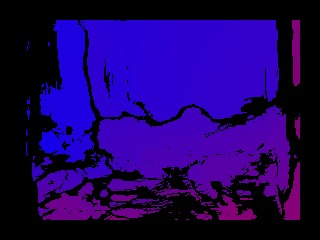
This disparity image was created using a single Rovio robot by taking pictures from two different locations.
I’m a bit late to the game of Rovio hacking, but here I am experimenting with using a Rovio I bought two years ago. The Rovio by Wowwee is a remote control car that has a camera mounted on it that can be controlled over wireless web based interface. When it was discontinued, the existing stock was liquidated in a fire sale, where they were sold for around $100 each. You can still buy them now, for about $400, on Amazon. Keep in mind you might need to buy a new battery and power supply.
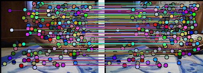
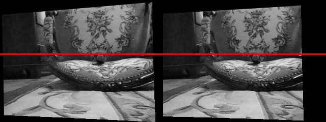
The figure to the left shows a disparity image created using a single Rovio by driving it a few inches to the right. In this disparity image warmer colors are closer and cooler colors are farther away. See below for the input images. From this disparity image you can create a point cloud, which can then be used for making 3D models or obstacle detection. This process is entirely automated using BoofCV and the source code is available online on my Rovio Github project:
Initial Setup
You will need to do the following once so that your camera is calibrated and that the software knows your robots parameters.
- Checkout source code from Github
- Calibrate the camera.
- Look at this first BoofCV Camera Calibration
- Collect images in 640×480 using ManualControlApp by pressing ‘m’
- Select good images, run calibration app. Pixel error should be around 0.3
- Get your robots MAC address using ManualControlApp by pressing ‘a’
- Create directory for your robot in robots. Place intrinsic.xml and file “mac” with the MAC address. See existing examples
Creating Point Cloud
Once you have done all of that all you need to do now is place the Rovio in a well lit room in front of something with lots of texture and run AutoPointCloudApp. That app will automatically figure out which robot it is controlling, loading calibration, collect and image, move the robot, and collect another image. The two images are then processed and the results displayed. Don’t forget to change the IP address in the main() function of AutoPointCloudApp.


